
SF Modules – Set 023 – Observation Devices – 01
SF Modules — Set 023 “Observation Devices”.
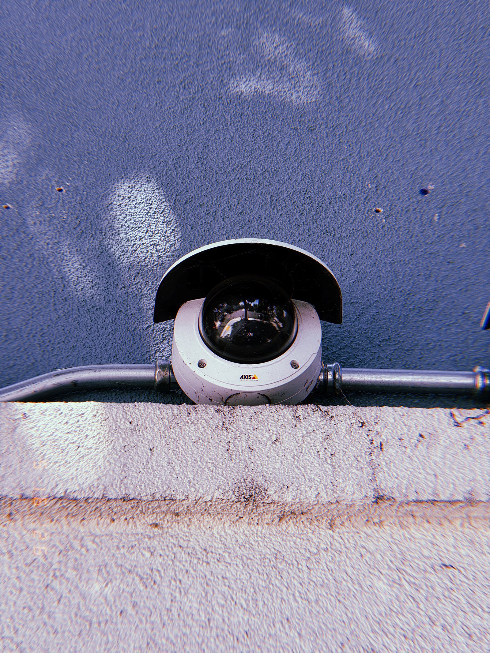
A dome surveillance camera is installed beneath a protective shield and connected to exposed metal conduit integrated into the building structure. Positioned along a wall junction, the device combines monitoring technology with supporting utility infrastructure. The camera operates as a fixed observation point within a distributed network of urban surveillance systems.
SF Modules – Set 023 – Observation Devices – 02
SF Modules — Set 023 “Observation Devices”.
A surveillance camera is installed on a rooftop surface beneath electrical conduits and utility infrastructure. The device projects a long shadow across the textured material, revealing its physical presence within the architectural environment. Positioned as part of a larger monitoring network, the camera extends observation capabilities across the surrounding urban landscape.

SF Modules – Set 023 – Observation Devices – 03
SF Modules — Set 023 “Observation Devices”.
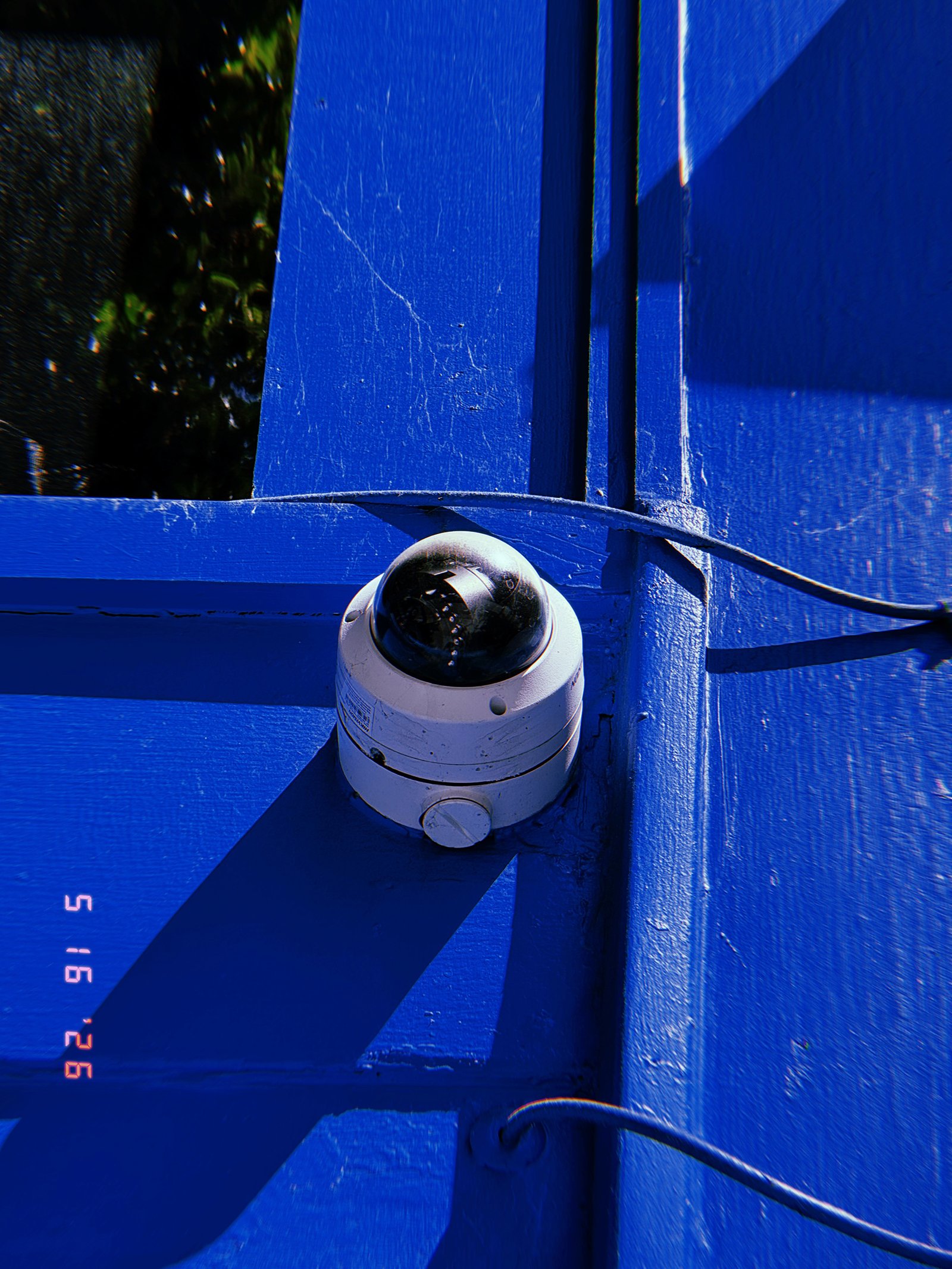
A dome surveillance camera is installed at the junction of structural elements on a brightly painted blue surface. Exposed wiring extends across the architecture, connecting the device to a wider monitoring network. Strong sunlight and sharp shadows reveal the camera as both a functional component and a visible element of urban observation infrastructure.
SF Modules – Set 023 – Observation Devices – 04
SF Modules — Set 023 “Observation Devices”.
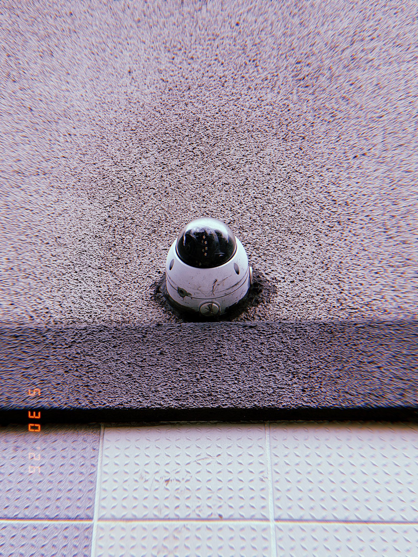
A compact dome surveillance camera is installed directly into a textured building facade above a tiled surface. Embedded at the junction of architectural materials, the device occupies a fixed position within the structure, extending observation functions into the surrounding urban environment. Weathering and surface wear indicate continuous operation over time.
SF Modules – Set 023 – Observation Devices – 05
SF Modules — Set 023 “Observation Devices”.
A compact surveillance camera is attached to a textured building facade, connected by an exposed cable that traces a visible path across the surface. Positioned within the architectural skin of the city, the device functions as a localized observation point while graffiti markings below introduce traces of human activity and intervention.

SF Modules – Set 023 – Observation Devices – 06
SF Modules — Set 023 “Observation Devices”.
A dome surveillance camera is mounted directly onto a textured building facade. Positioned above utility hardware and integrated into the architectural surface, the device extends observation capabilities into the immediate surroundings. Signs of weathering and accumulated wear reveal the long-term presence of monitoring infrastructure within the urban environment.
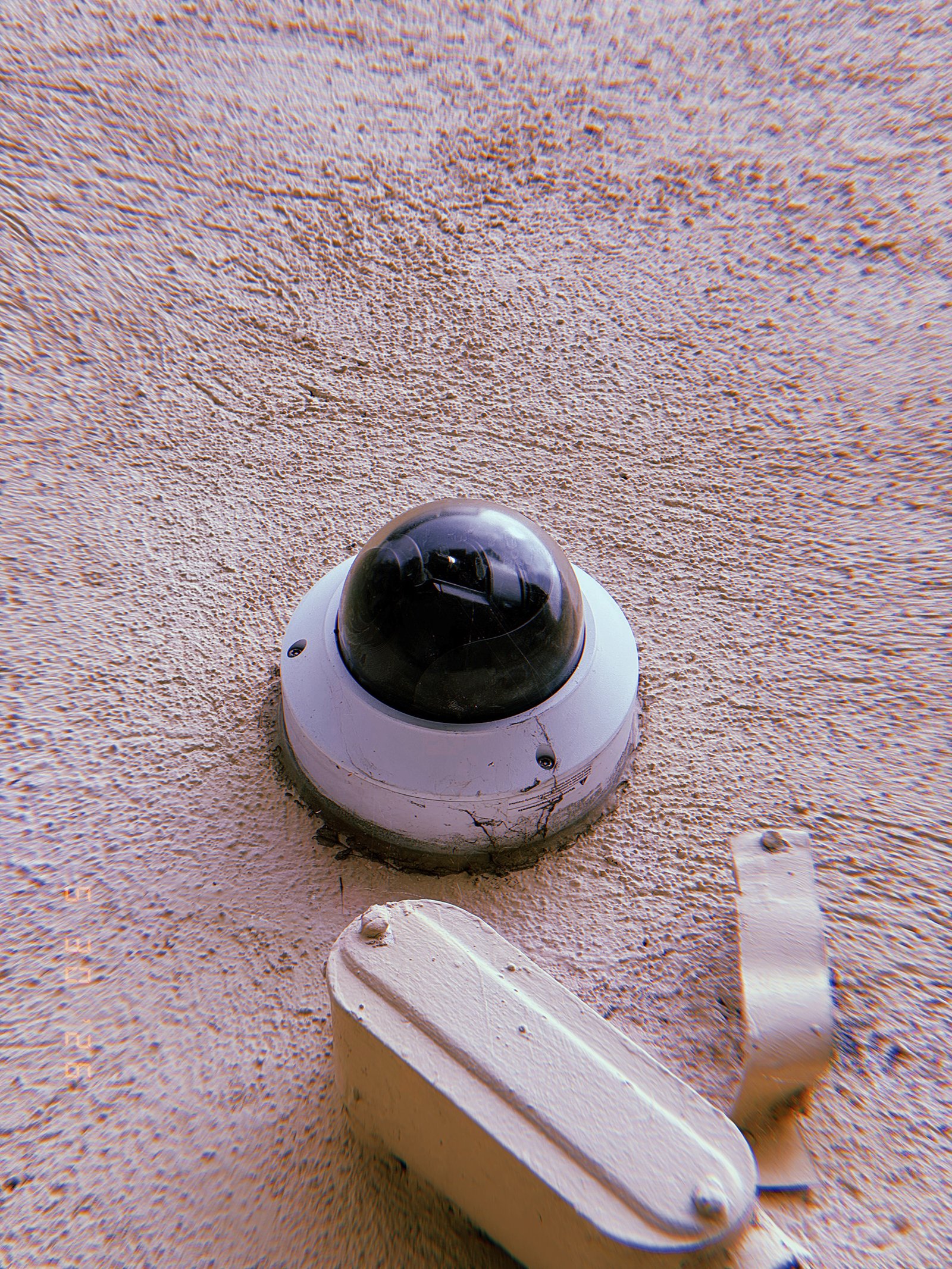
SF Modules – Set 023 – Observation Devices – 07
SF Modules — Set 023 “Observation Devices”.
A surveillance camera is installed flush against a building surface, reducing the distance between observation infrastructure and the space being monitored. Unlike fully opaque dome housings, the transparent enclosure exposes parts of the internal optical system while maintaining physical protection. The device functions as a visible point of observation embedded directly within the urban environment.
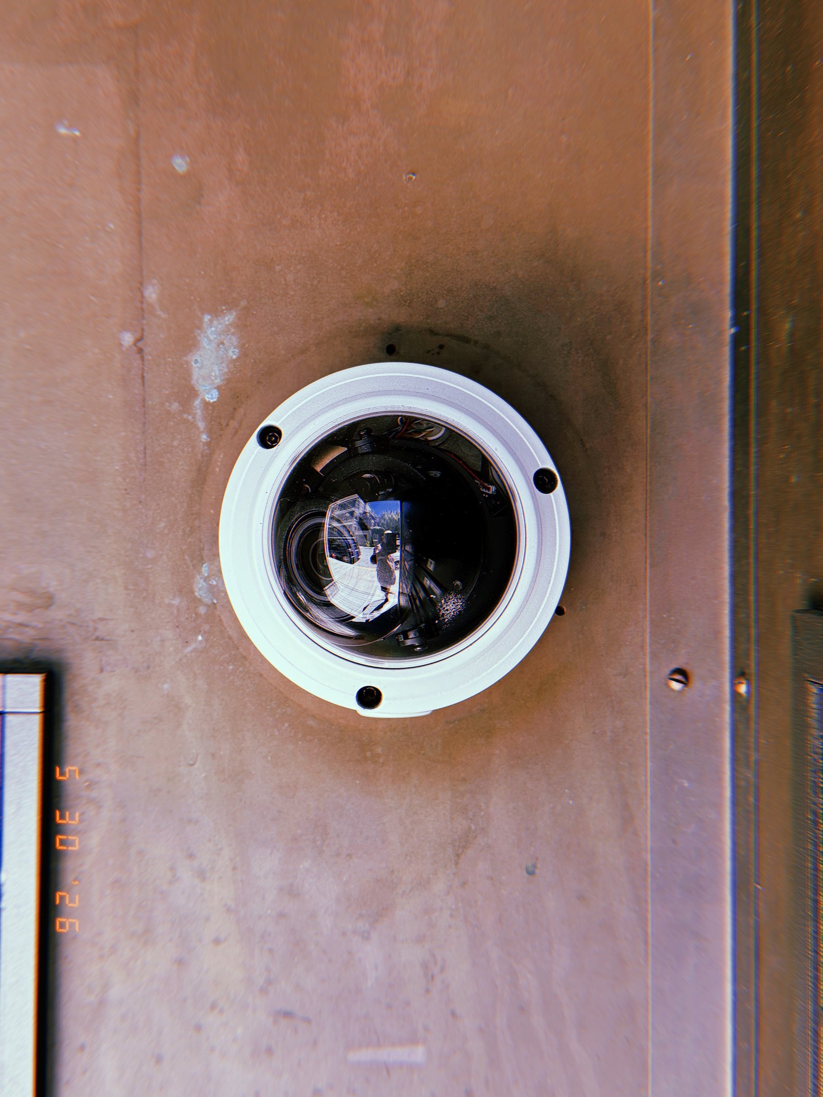
SF Modules – Set 023 – Observation Devices – 08
SF Modules — Set 023 “Observation Devices”.
A surveillance camera is positioned above a window and protective metal bars, extending observation beyond the physical boundary of the building. The elevated placement provides continuous visibility of the surrounding area while the reflective dome conceals the precise direction of monitoring. Observation is integrated into the architecture as a permanent operational layer.
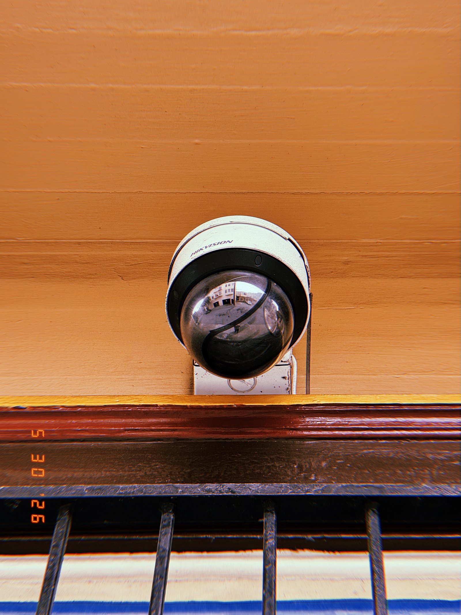
SF Modules – Set 023 – Observation Devices – 09
SF Modules — Set 023 “Observation Devices”.
A surveillance camera is installed at the edge of a building facade, positioned to maximize its field of view across multiple directions. The dark reflective dome conceals the orientation of the lens while simultaneously reflecting the environment it monitors. Observation remains visible as infrastructure, but the specific act of watching is obscured within the device itself.

SF Modules – Set 022 – Private Property Systems – 01
SF Modules — Set 022 “Private Property Systems”.
A standardized prohibition sign is attached directly to a residential garage door. The instruction is integrated into the architectural surface it protects, linking the restriction to a specific property address and access point. Through a simple visual command, the sign establishes control over a small but essential component of private space.

SF Modules – Set 022 – Private Property Systems – 02
SF Modules — Set 022 “Private Property Systems”.
A standardized prohibition sign is fixed to an otherwise unmarked wall surface. Removed from the complexity of municipal parking regulations, the instruction operates as a direct declaration of property control. The sign establishes a private boundary through a minimal visual language that is immediately recognizable and universally understood.
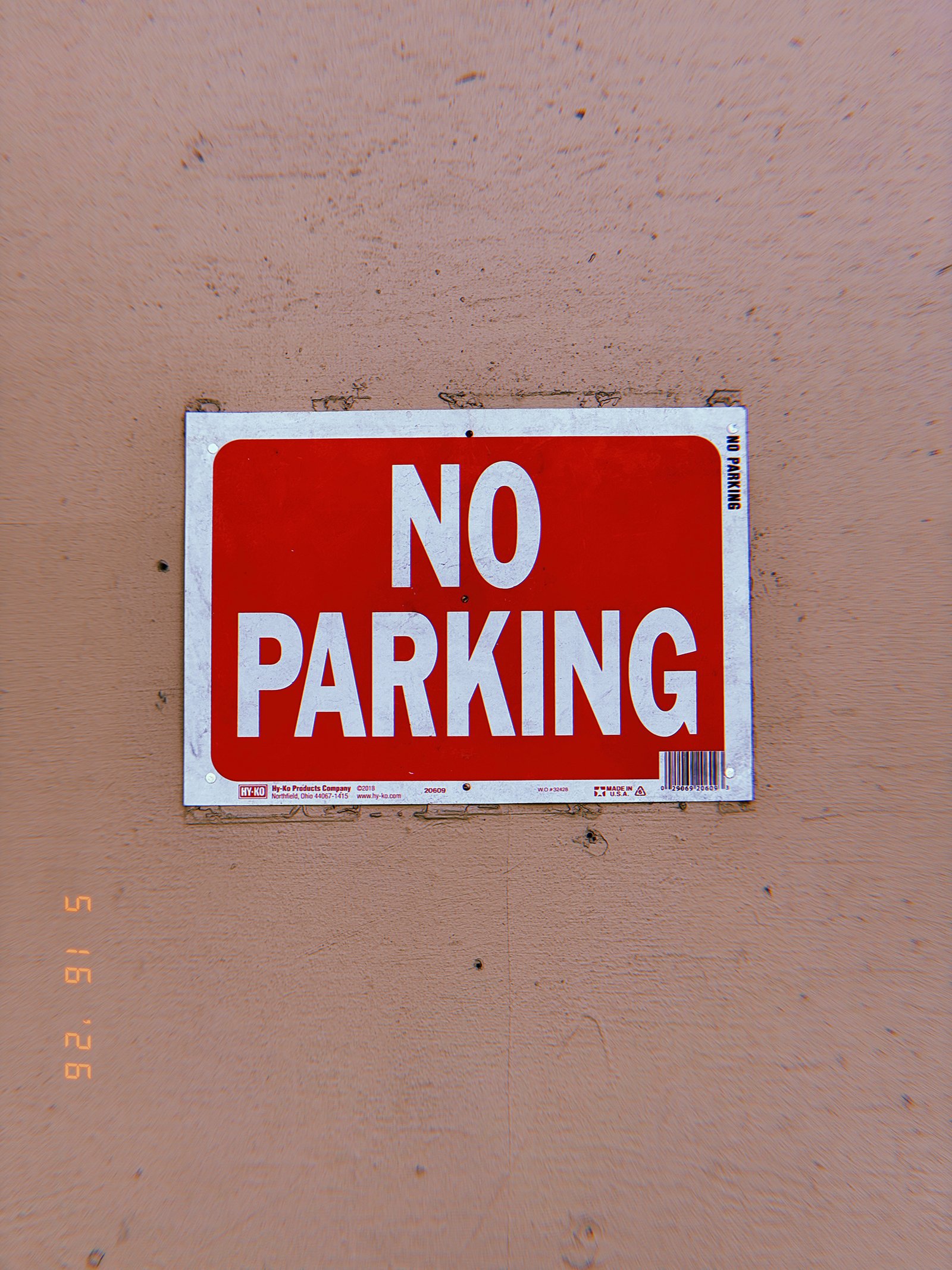
SF Modules – Set 022 – Private Property Systems – 03
SF Modules — Set 022 “Private Property Systems”.
A standardized prohibition sign is integrated into the center of a residential garage door. Framed by the door’s repeating geometric panels and changing patterns of light and shadow, the instruction remains constant. The sign functions as a simple access-control device, marking the driveway as a protected component of private property.
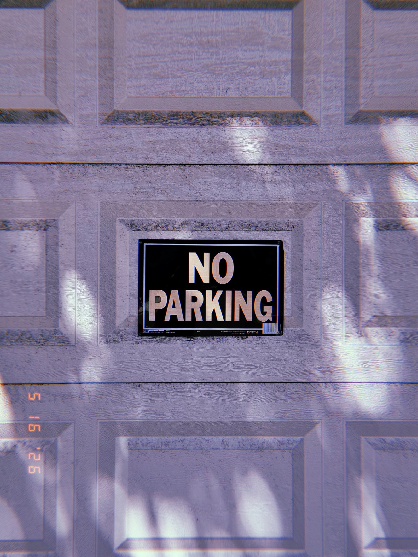
SF Modules – Set 022 – Private Property Systems – 04
SF Modules — Set 022 “Private Property Systems”.
A standardized prohibition sign is attached to a temporary plywood surface. Unlike municipal parking regulations that specify times and conditions, this instruction is absolute and self-contained. The sign establishes a private boundary through a minimal visual command, requiring no further context to operate.
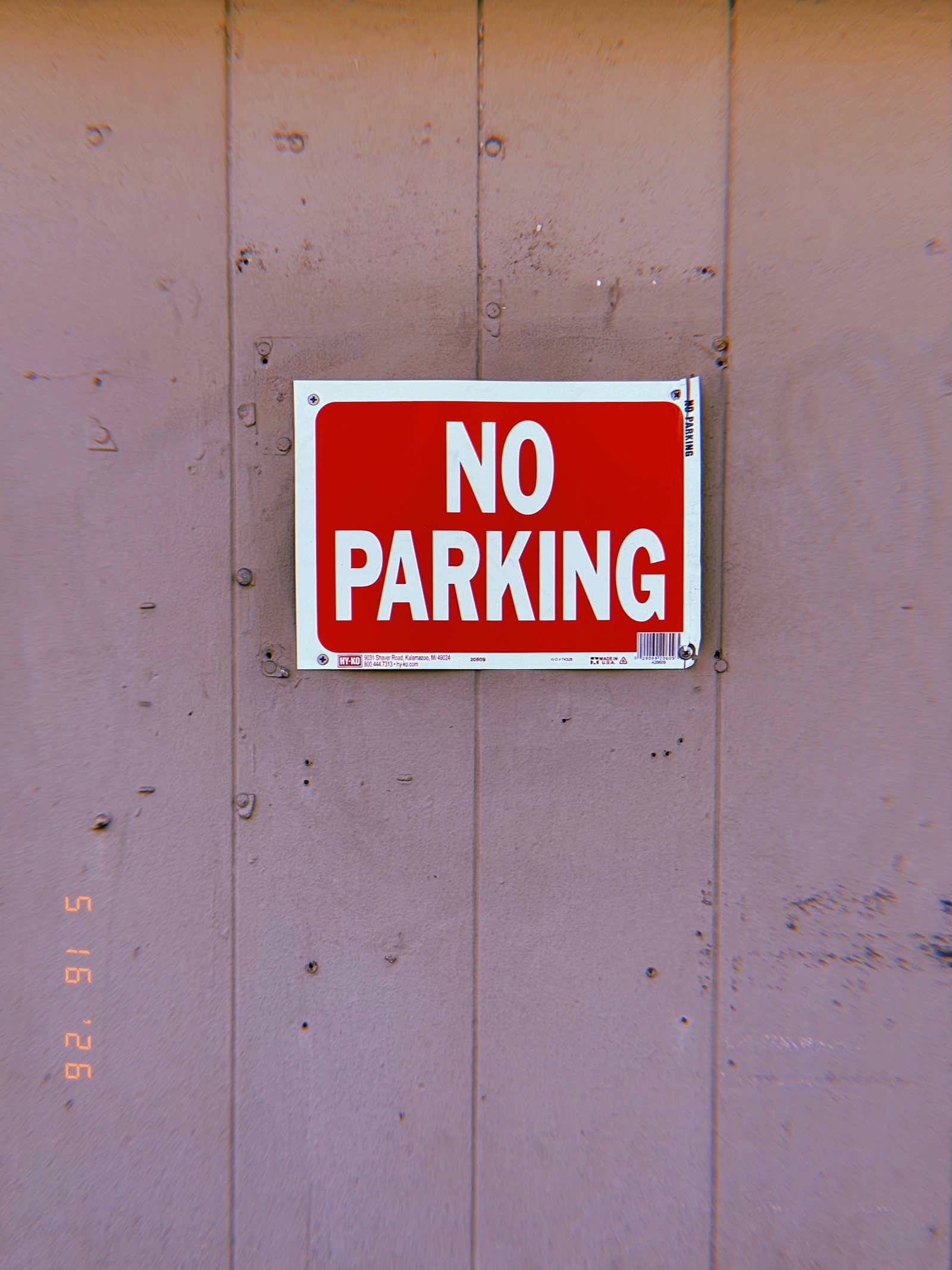
SF Modules – Set 022 – Private Property Systems – 05
SF Modules — Set 022 “Private Property Systems”.
A standardized access restriction is positioned directly on a private garage door. Subsequent markings and graffiti accumulate on the sign, creating a visible record of interaction while leaving the underlying instruction intact. The system remains operational despite modification, continuing to define the boundary between public use and private access.

SF Modules – Set 022 – Private Property Systems – 06
SF Modules — Set 022 “Private Property Systems”.
A regulatory marker is integrated directly into a private access point. The instruction defines a condition of exclusion that preserves the operational function of the driveway while preventing unauthorized occupation of the space immediately in front of it. The sign serves as a simple interface between public street use and private property control.

SF Modules – Set 022 – Private Property Systems – 07
SF Modules — Set 022 “Private Property Systems”.
A standardized exclusion marker is attached directly to a private boundary structure. The instruction regulates the use of adjacent space by prohibiting vehicle occupation and reinforcing the operational requirements of the property it protects. The sign functions as a simple interface between public circulation and private control.

SF Modules – Set 022 – Private Property Systems – 08
SF Modules — Set 022 “Private Property Systems”.
A minimal regulatory marker communicates a condition of exclusion within a privately controlled environment. By restricting vehicle occupancy, the sign preserves access and operational function while reinforcing the boundary between public circulation space and private property requirements.

SF Modules – Set 022 – Private Property Systems – 09
SF Modules — Set 022 “Private Property Systems”.
A simple regulatory marker defines the boundary between public street space and private access infrastructure. The sign communicates an exclusion condition, protecting the operational function of the driveway and maintaining uninterrupted access to the property beyond.

SF Modules – Set 021 – Street Regulation Systems – 01
SF Modules — Set 021 “Street Regulation Systems”.
A standardized sign assembly coordinates multiple rules governing the use of public curb space. Maintenance schedules, parking duration limits, and permit-based exceptions are combined into a single regulatory interface that organizes vehicle turnover, resident access, and municipal operations within the urban environment.
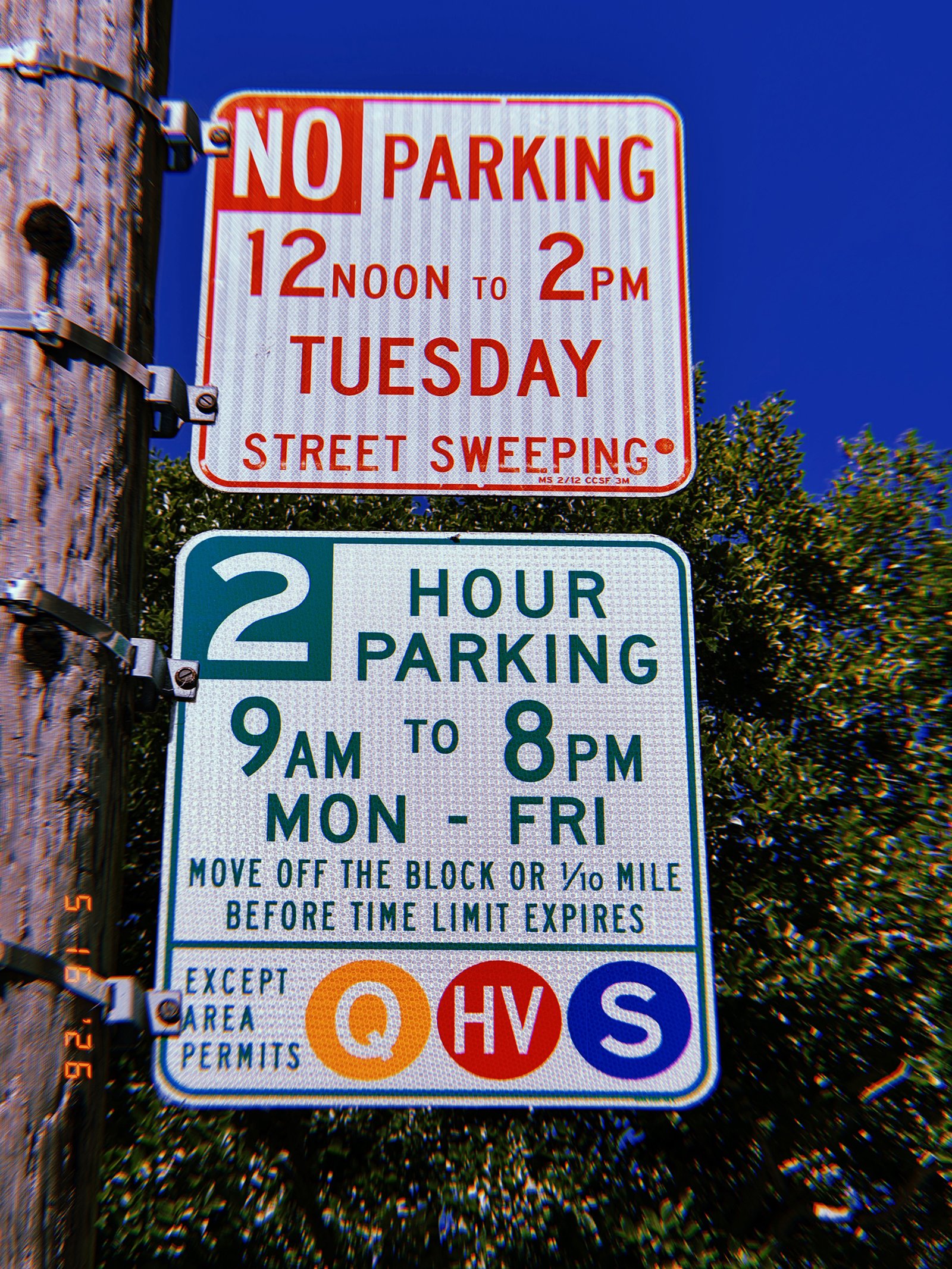
SF Modules – Set 021 – Street Regulation Systems – 02
SF Modules — Set 021 “Street Regulation Systems”.
A single sign assembly communicates multiple regulatory conditions governing the use of curb space. Scheduled maintenance periods, parking duration limits, and permit-based exemptions are layered into a unified instruction system that organizes vehicle occupancy and supports municipal operations within the street network.
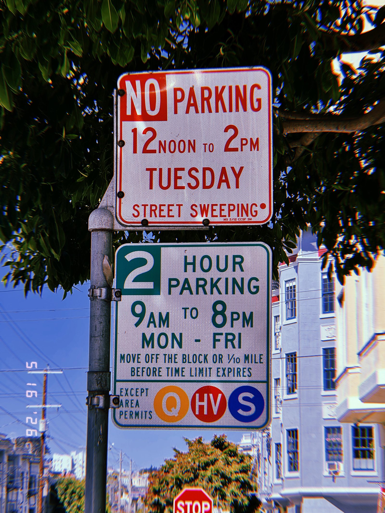
SF Modules – Set 021 – Street Regulation Systems – 03
SF Modules — Set 021 “Street Regulation Systems”.
A layered sign assembly defines multiple conditions for occupying public curb space. Temporary restrictions support municipal maintenance operations, while time limits and permit exceptions regulate vehicle turnover and resident access. The system balances circulation, access, and service requirements through standardized visual instructions.
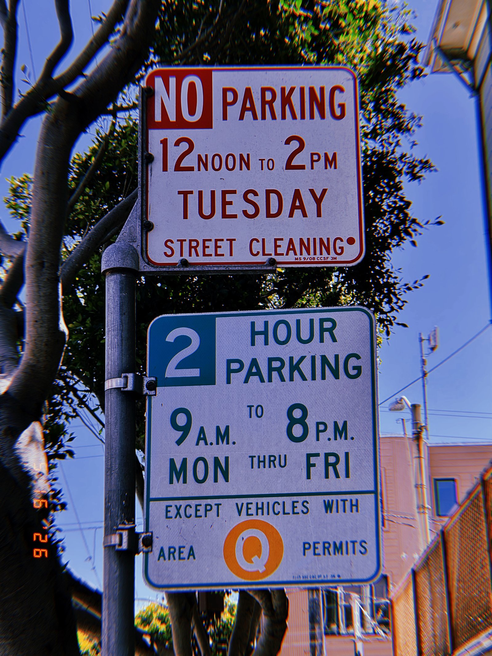
SF Modules – Set 021 – Street Regulation Systems – 04
SF Modules — Set 021 “Street Regulation Systems”.
Multiple regulatory layers are combined within a single sign assembly to control the use of public curb space. Time-based parking limits, permit exemptions, and scheduled street maintenance periods operate together to manage vehicle turnover, neighborhood access, and municipal service operations.
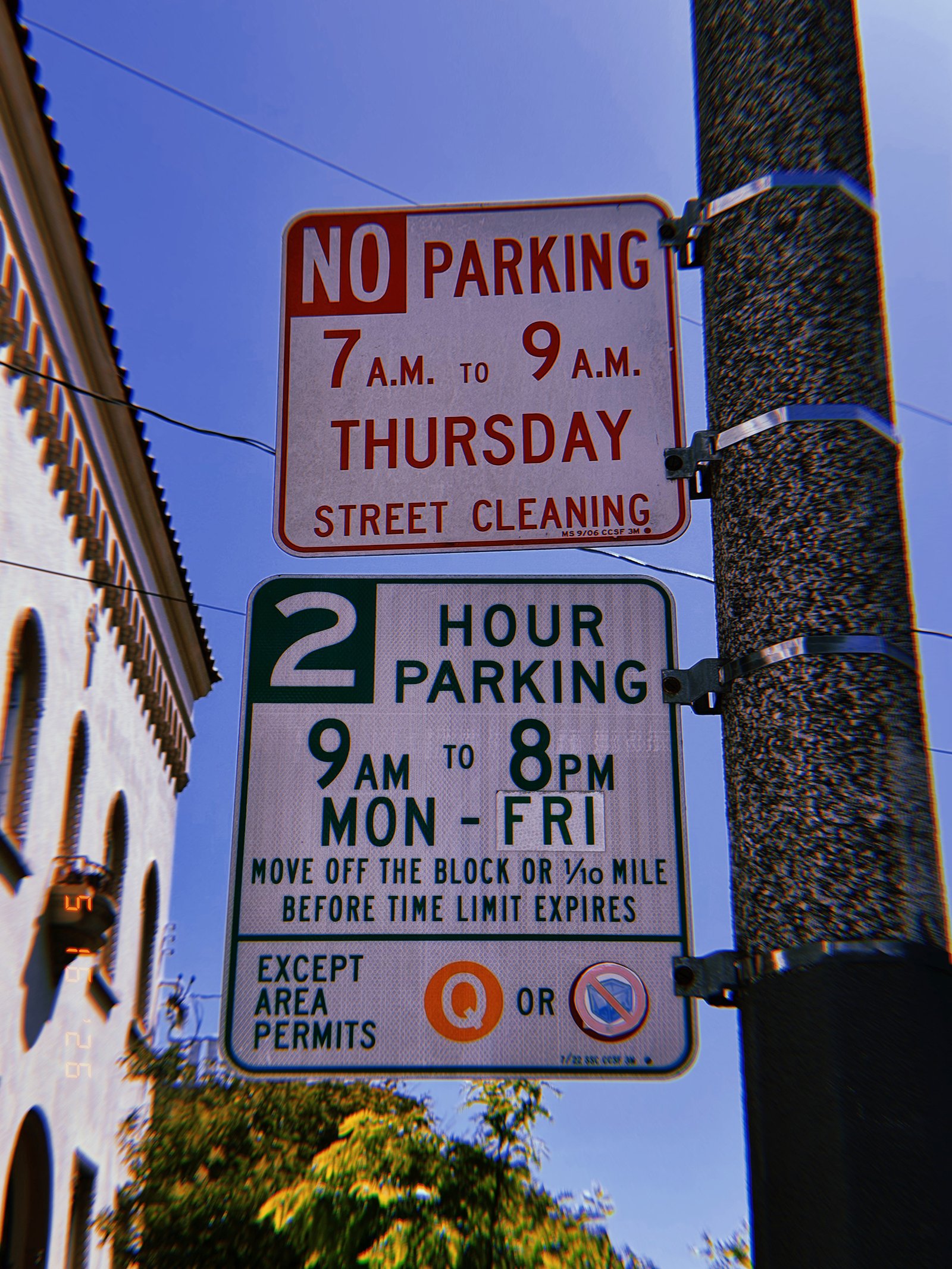
SF Modules – Set 021 – Street Regulation Systems – 05
SF Modules — Set 021 “Street Regulation Systems”.
Parking restrictions, maintenance schedules, and permit-based exceptions are combined within a single regulatory assembly controlling the use of curb space. Through coordinated time limits and access rules, the system balances vehicle turnover, street maintenance operations, and local parking privileges within the urban environment.
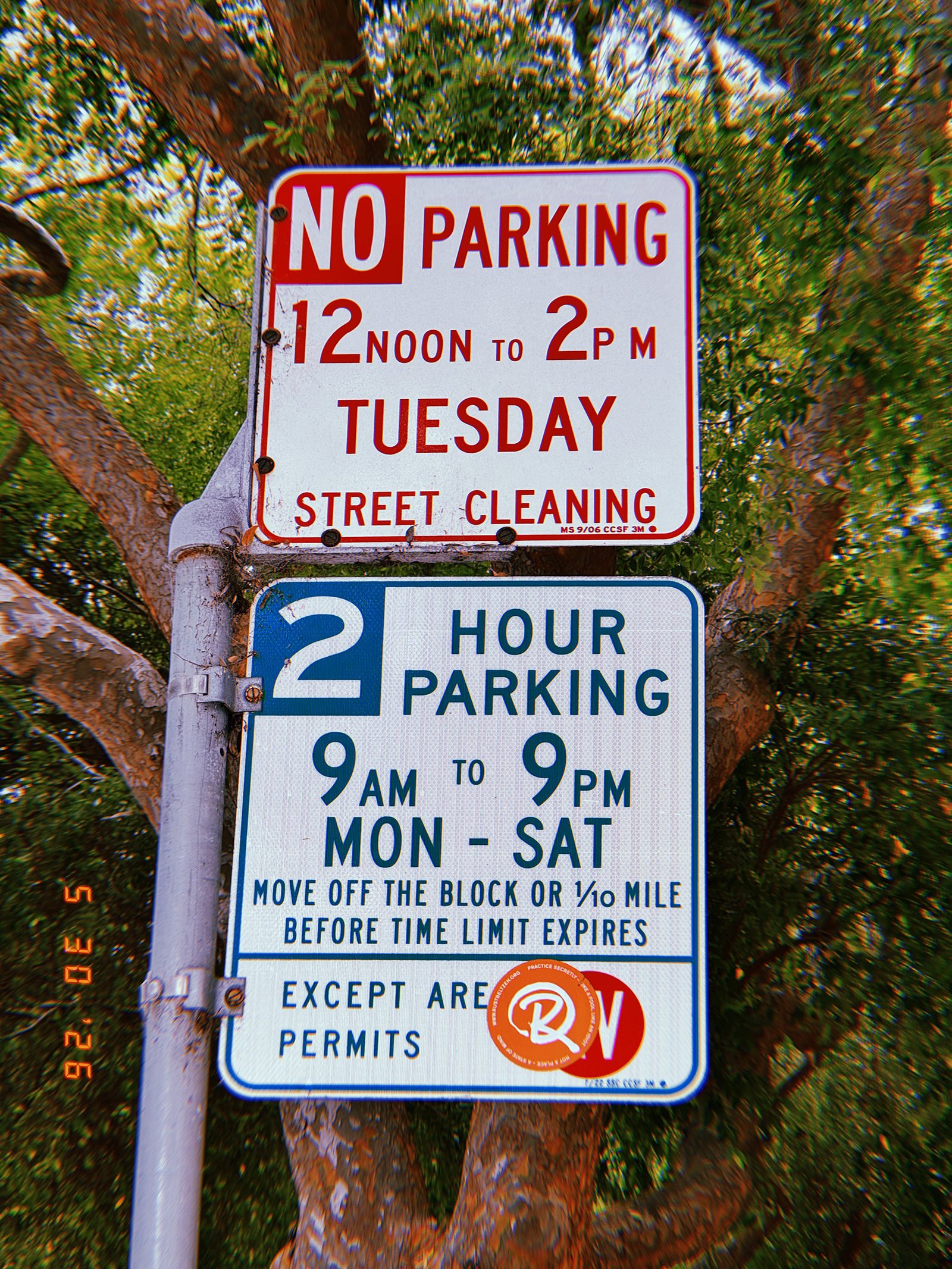
SF Modules – Set 021 – Street Regulation Systems – 06
SF Modules — Set 021 “Street Regulation Systems”.
Street cleaning schedules, parking duration limits, and residential permit exceptions are coordinated through a layered regulatory sign system. The assembly manages access to curb space by balancing maintenance operations, vehicle turnover, and local parking privileges within the urban street network.
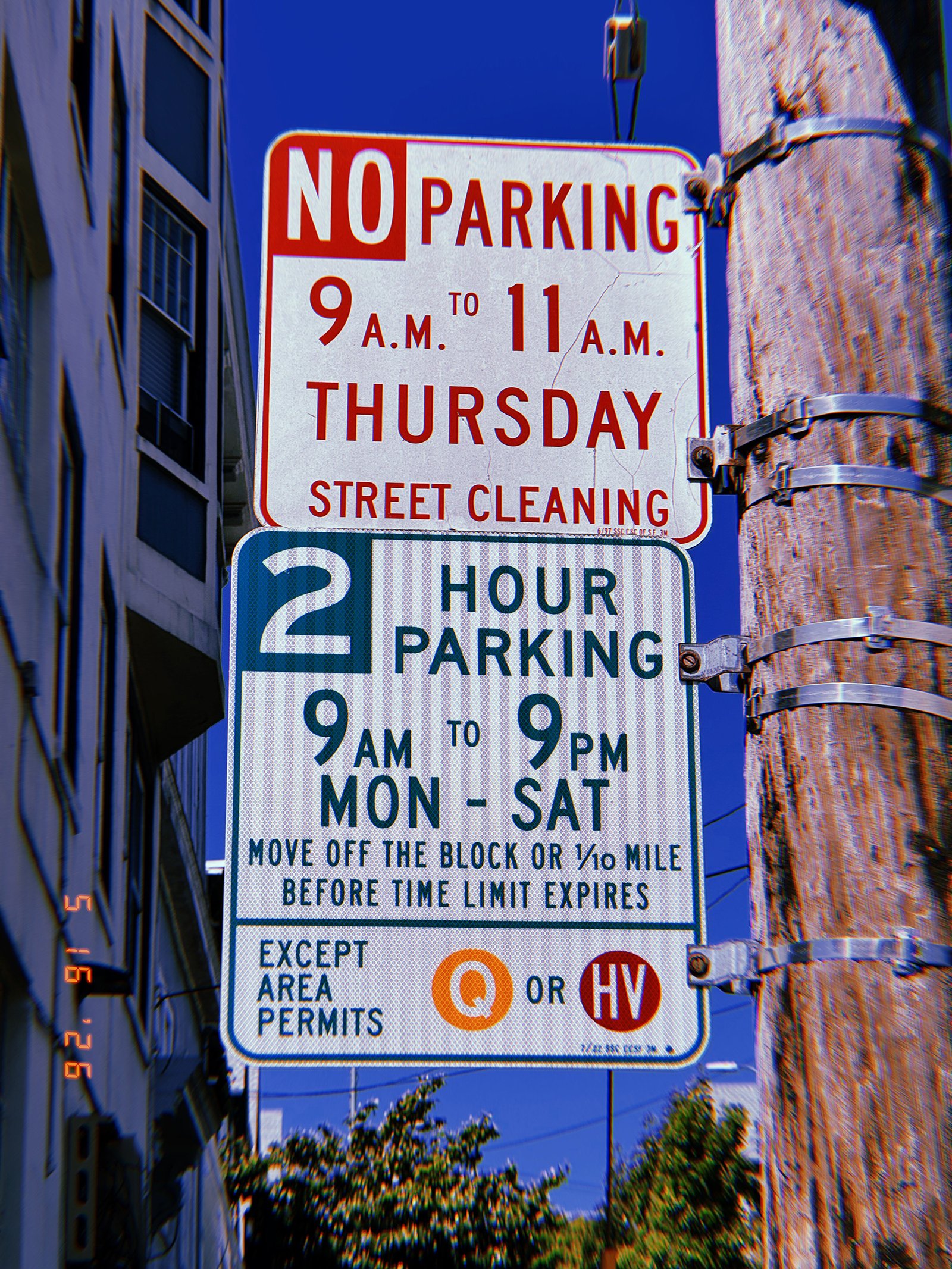
SF Modules – Set 021 – Street Regulation Systems – 07
SF Modules — Set 021 “Street Regulation Systems”.
Street maintenance schedules, parking duration limits, and permit-based access controls are integrated into a single regulatory structure. The sign assembly governs how public curb space may be occupied, coordinating circulation, maintenance operations, and resident access through a system of timed restrictions and exemptions.
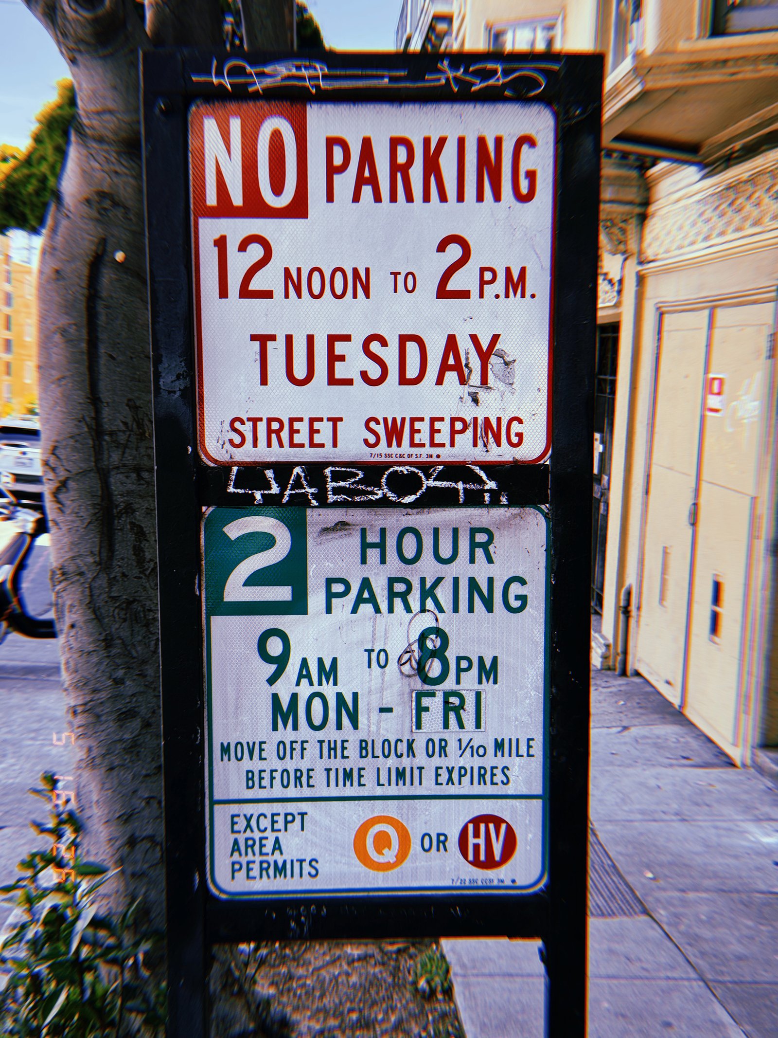
SF Modules – Set 021 – Street Regulation Systems – 08
SF Modules — Set 021 “Street Regulation Systems”.
Parking duration limits, maintenance schedules, and permit classifications are consolidated into a single regulatory interface governing the temporary occupation of public space. The sign assembly coordinates circulation, access, and street maintenance through a layered system of time-based restrictions and exemptions.
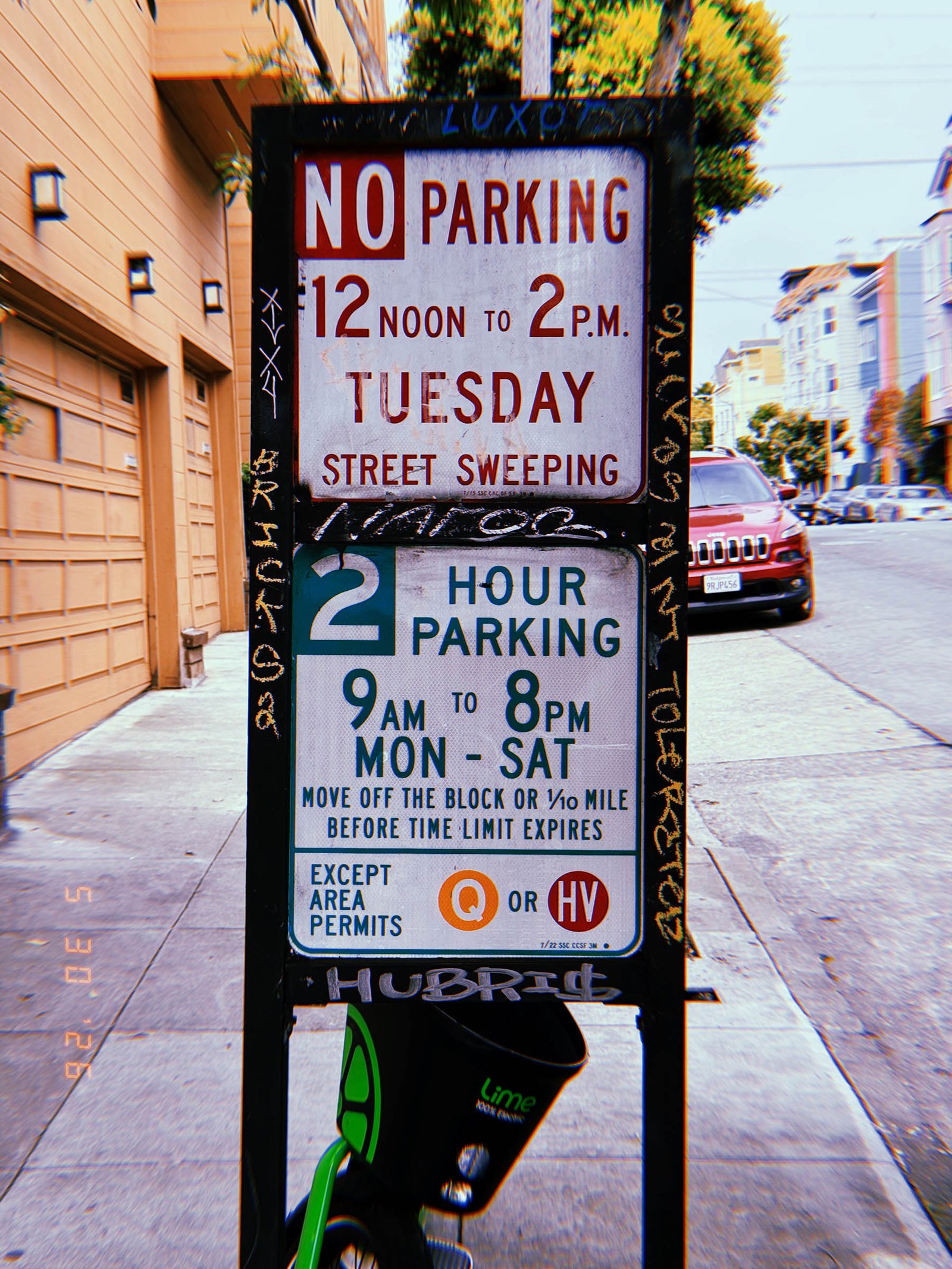
SF Modules – Set 021 – Street Regulation Systems – 09
SF Modules — Set 021 “Street Regulation Systems”.
Multiple parking regulations are consolidated within a layered sign assembly that governs access, duration, and maintenance requirements within the public street environment. Time restrictions, permit exemptions, and street cleaning schedules operate together as a coordinated regulatory interface directing the use of urban space.
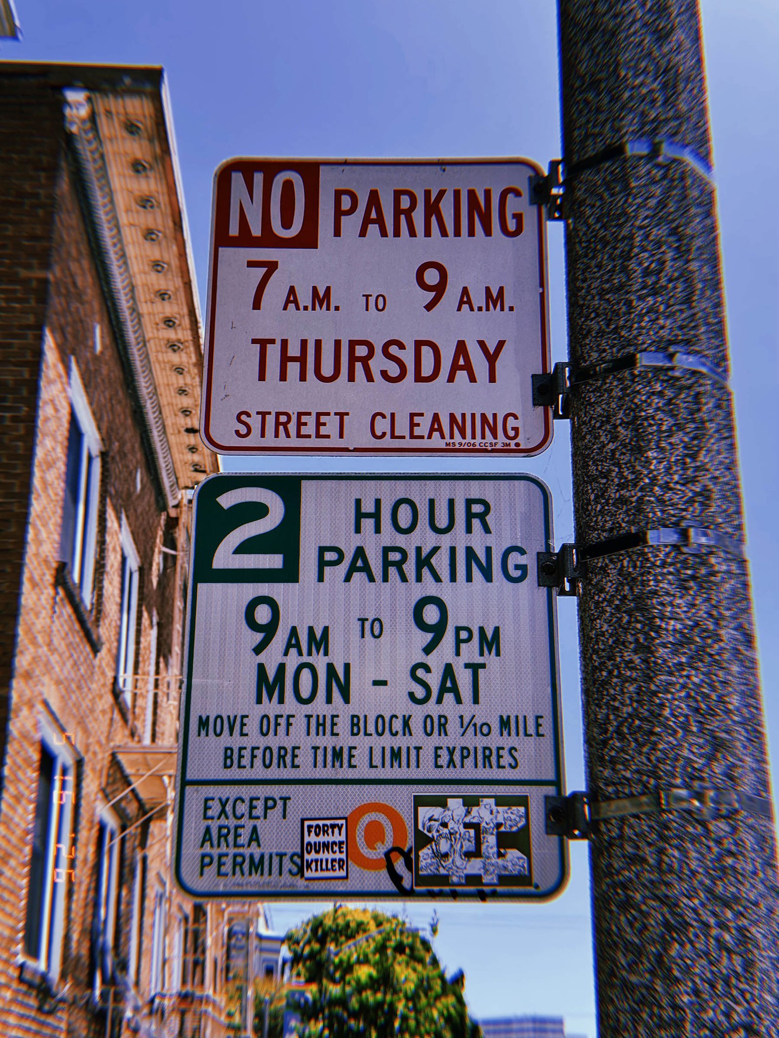
SF Modules – Set 020 – Electric Meter Systems – 01
SF Modules — Set 020 “Electric Meter Systems”.
Electrical consumption is measured through a series of digital smart meters integrated into a secured utility enclosure. The arrangement consolidates multiple service connections within a controlled access system, linking individual users to the broader electrical distribution network while maintaining separation, measurement, and administrative oversight.
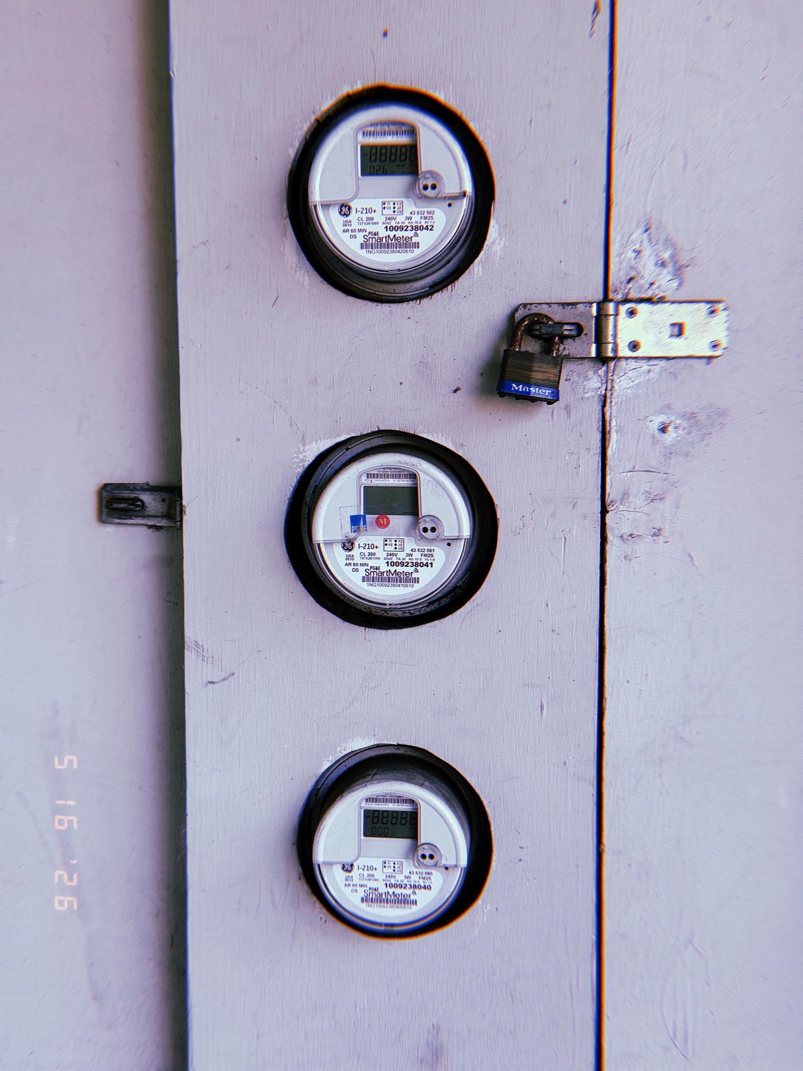
SF Modules – Set 020 – Electric Meter Systems – 02
SF Modules — Set 020 “Electric Meter Systems”.
A multi-tenant electrical distribution assembly organizes measurement, access control, and service separation within a single utility enclosure. Individual smart meters record electrical consumption while disconnect devices and secured access points regulate the relationship between users and the electrical network.
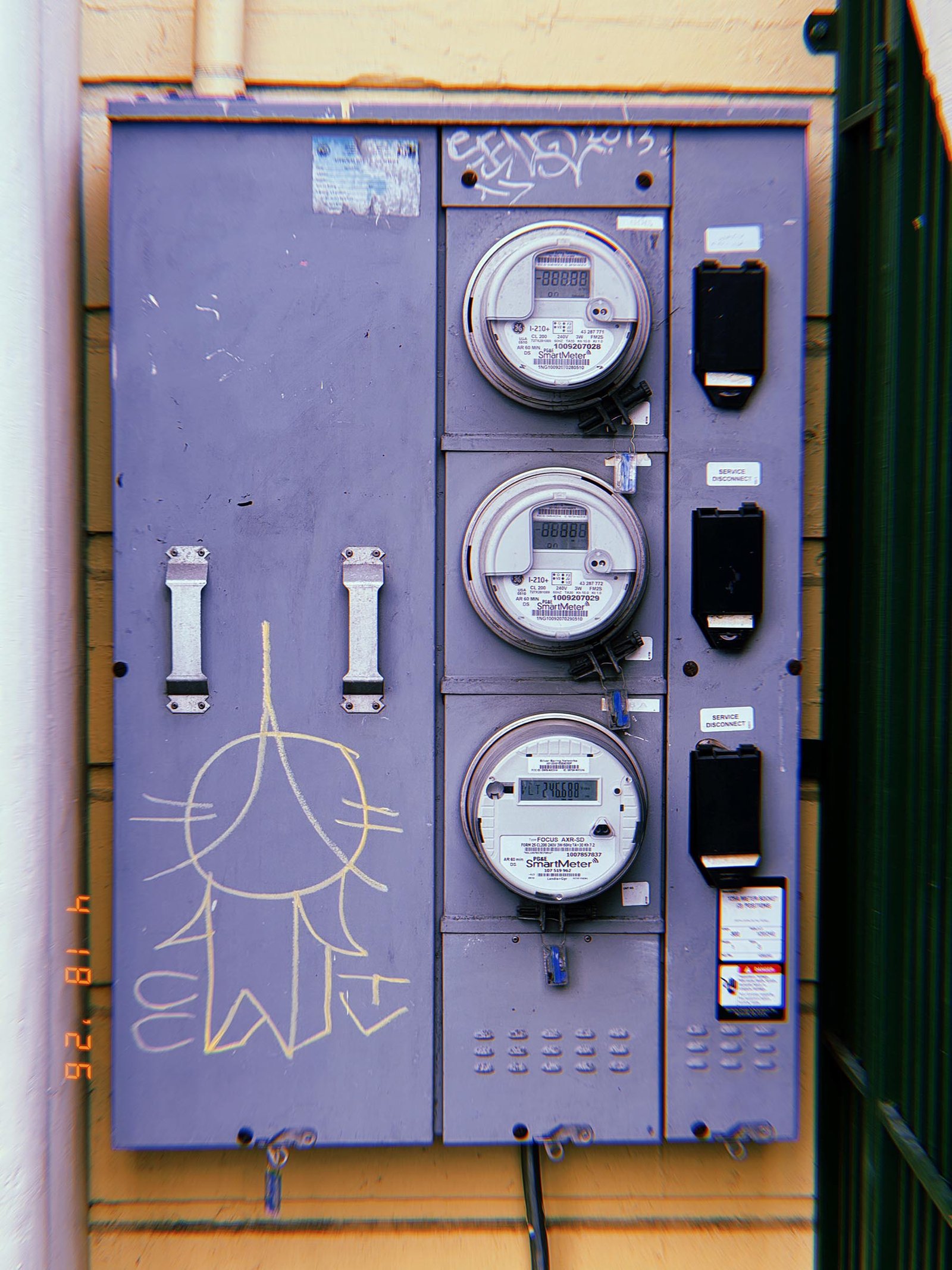
SF Modules – Set 020 – Electric Meter Systems – 03
SF Modules — Set 020 “Electric Meter Systems”.
Multiple electrical service connections are consolidated within a shared distribution cabinet containing digital smart meters and supporting electrical infrastructure. The installation functions as a measurement and allocation interface, recording energy consumption for individual units while connecting them to the broader urban electrical network.
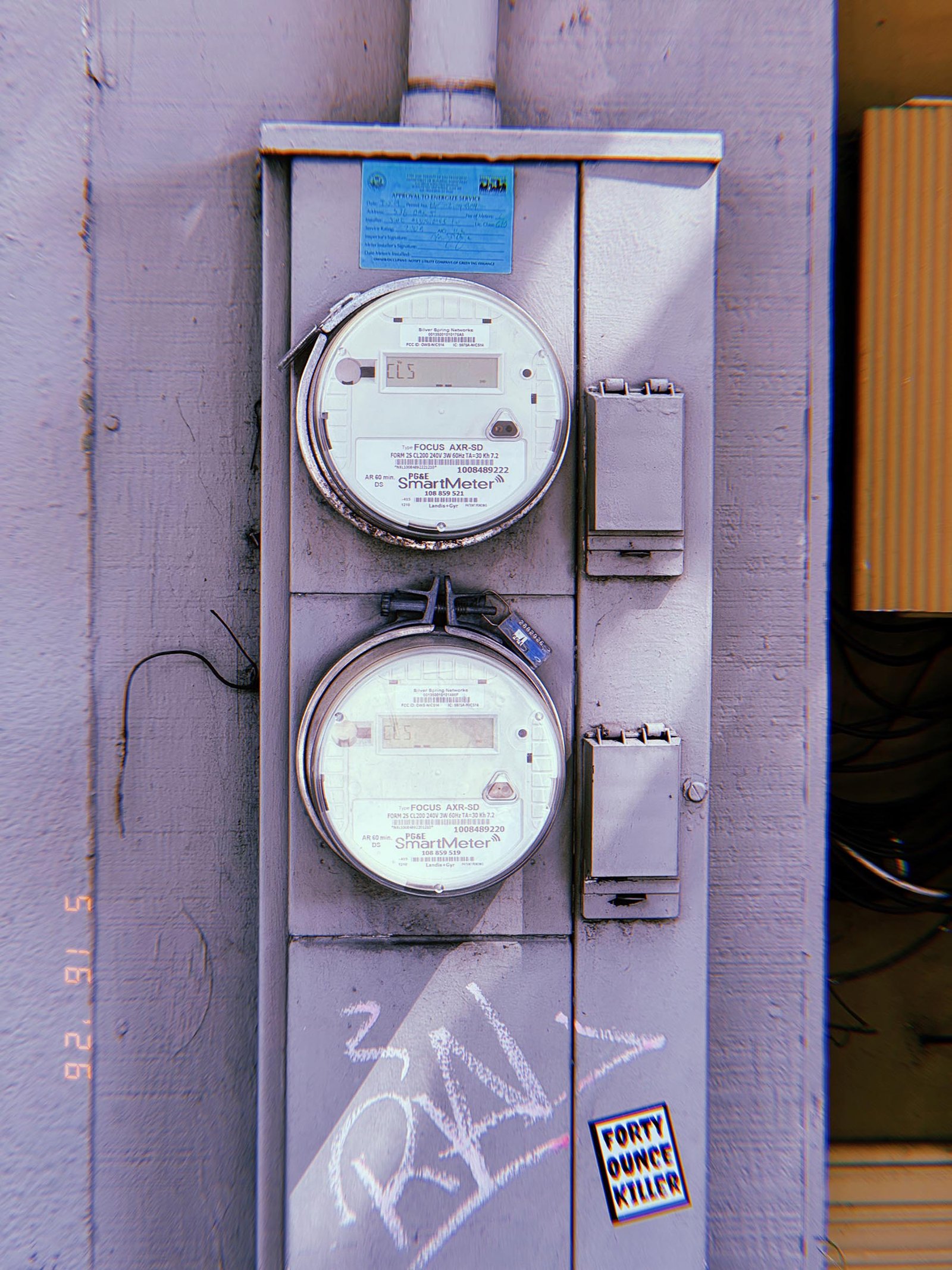
SF Modules – Set 020 – Electric Meter Systems – 04
SF Modules — Set 020 “Electric Meter Systems”.
Electrical consumption is monitored through a digital smart meter integrated into a secured service cabinet connected to the building distribution network. The meter functions as a measurement interface between the property and the utility system, recording energy use and supporting the allocation of electrical resources within the urban infrastructure.
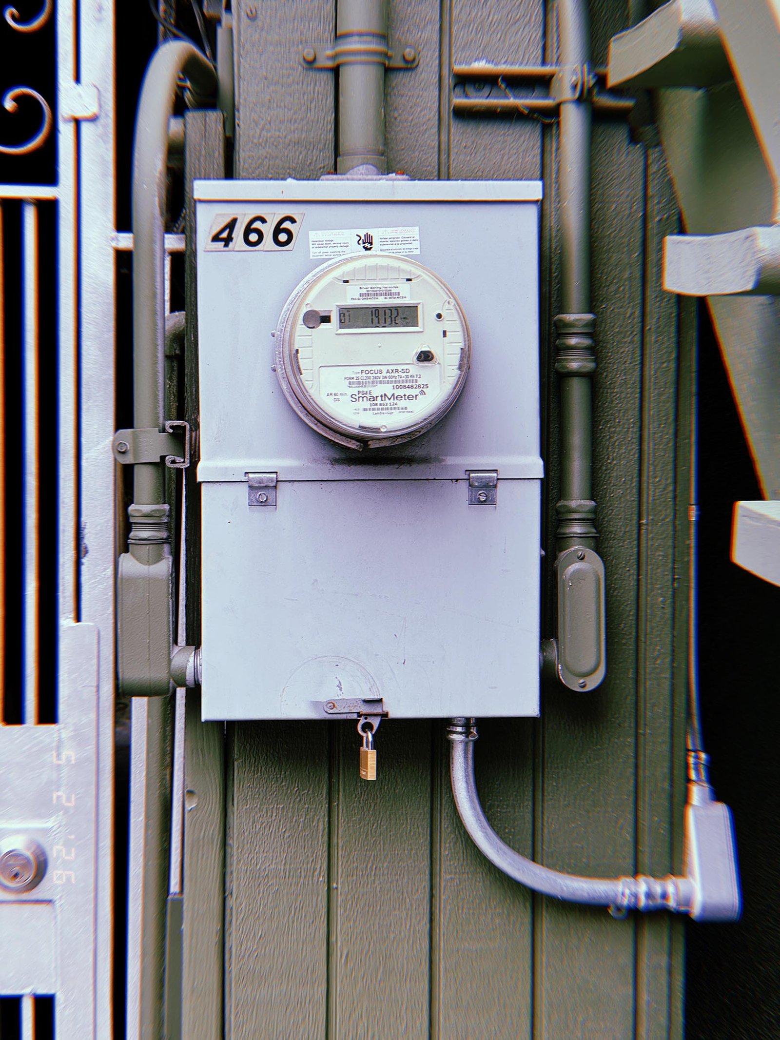
SF Modules – Set 020 – Electric Meter Systems – 05
SF Modules — Set 020 “Electric Meter Systems”.
Electrical consumption is measured through a digital smart meter installed within a protected service enclosure connected to the building distribution network. The device records energy usage and functions as an interface between individual consumption and the larger utility infrastructure responsible for monitoring and distribution.
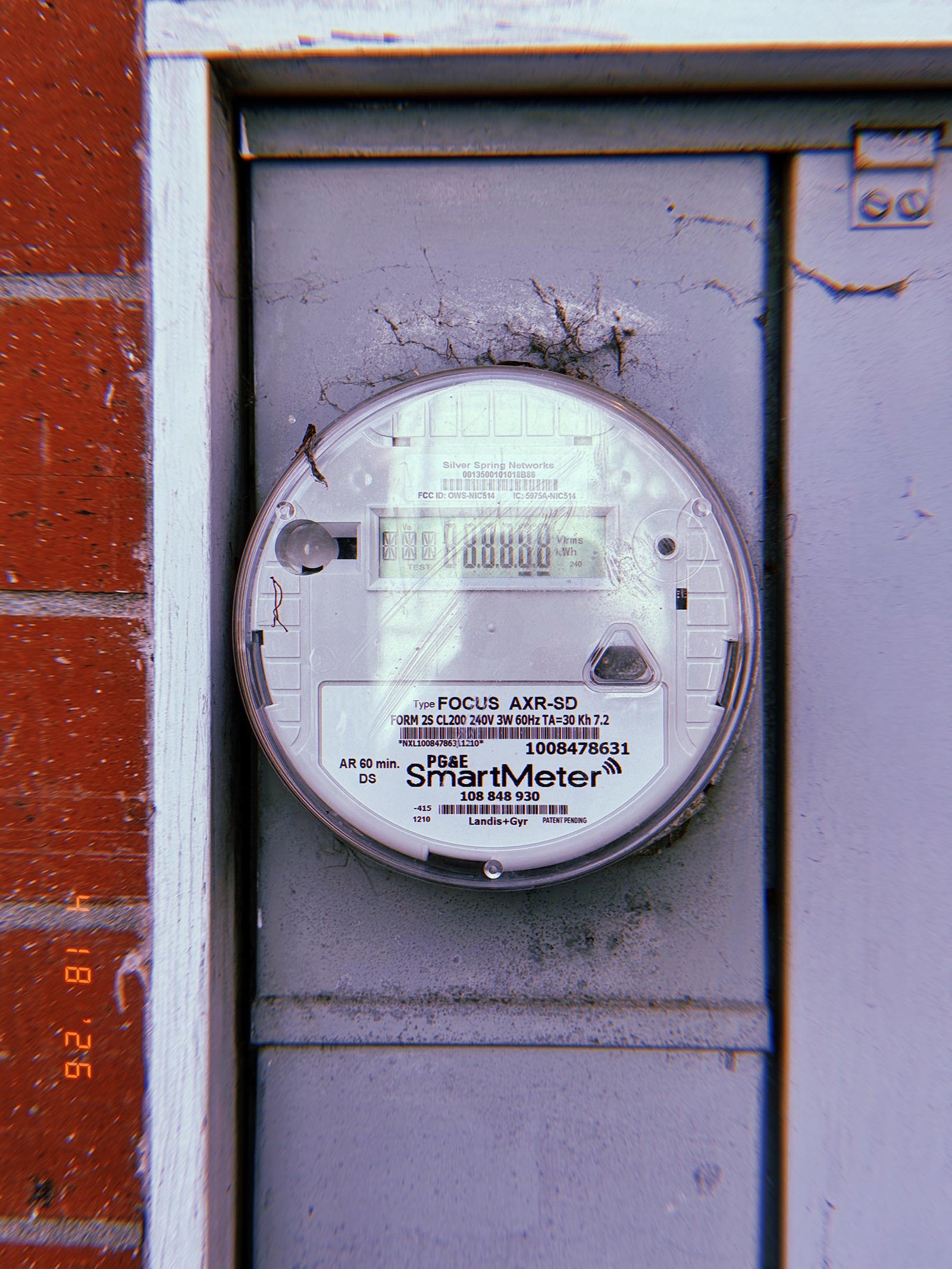
SF Modules – Set 020 – Electric Meter Systems – 06
SF Modules — Set 020 “Electric Meter Systems”.
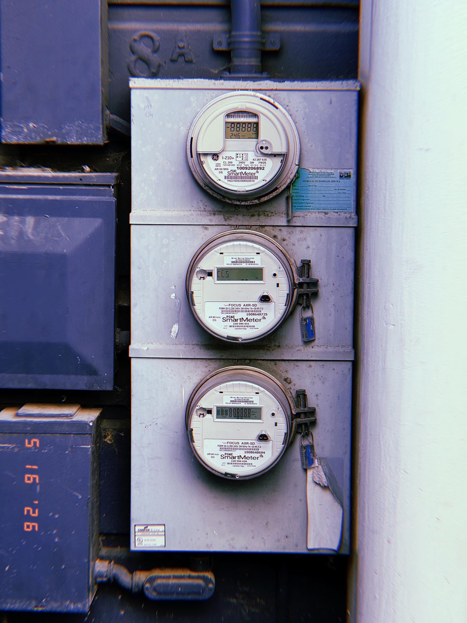
Electrical consumption is measured through a series of digital smart meters connected to individual service connections within a shared distribution system. The vertical arrangement separates utility monitoring by unit while maintaining integration with the larger electrical infrastructure serving the building.
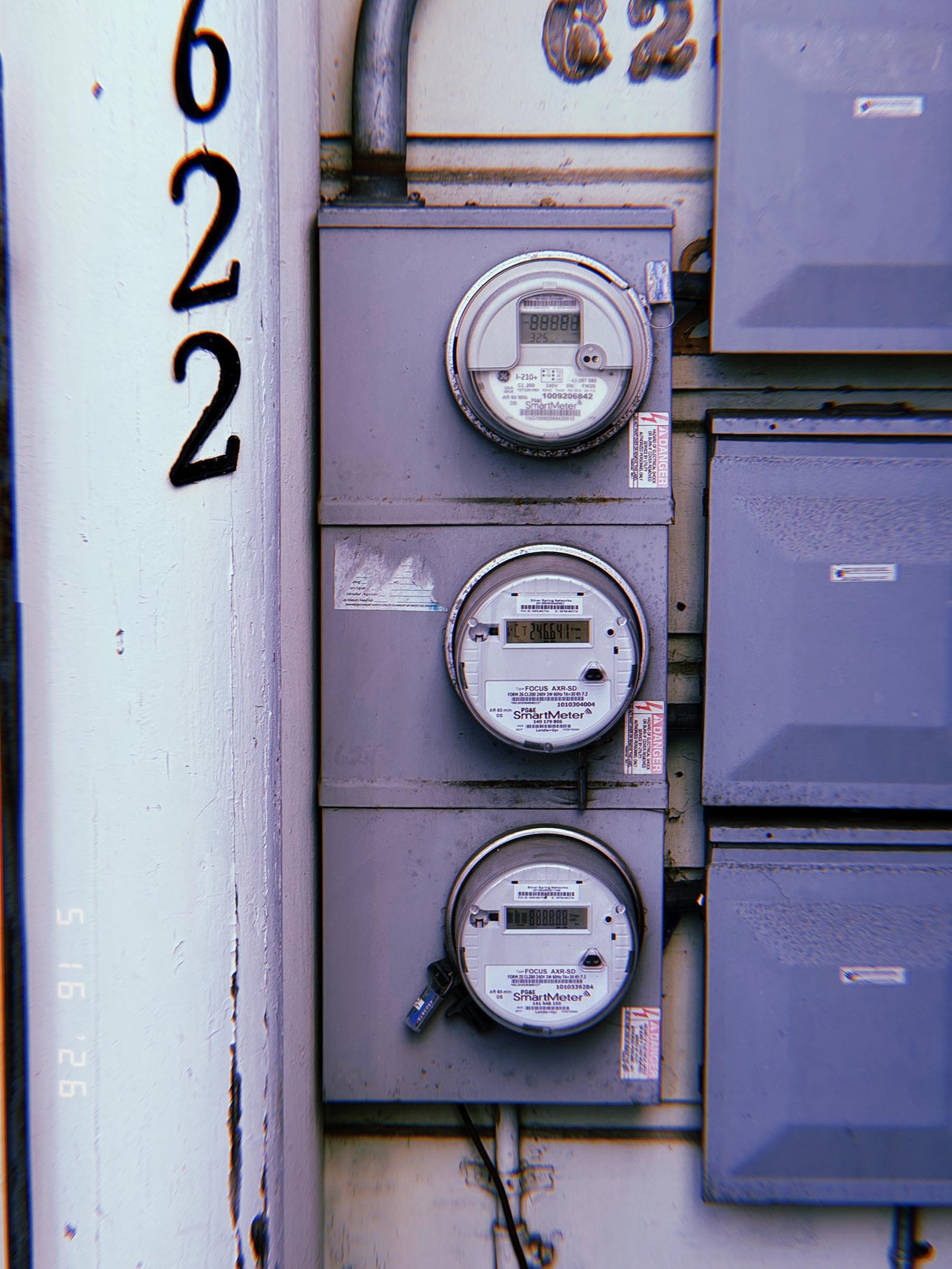
SF Modules – Set 020 – Electric Meter Systems – 07
SF Modules — Set 020 “Electric Meter Systems”.
Electrical consumption is measured through multiple smart meters integrated into a centralized distribution cabinet. The arrangement separates and records energy use across individual service connections while maintaining a unified interface between the building and the broader electrical utility network.
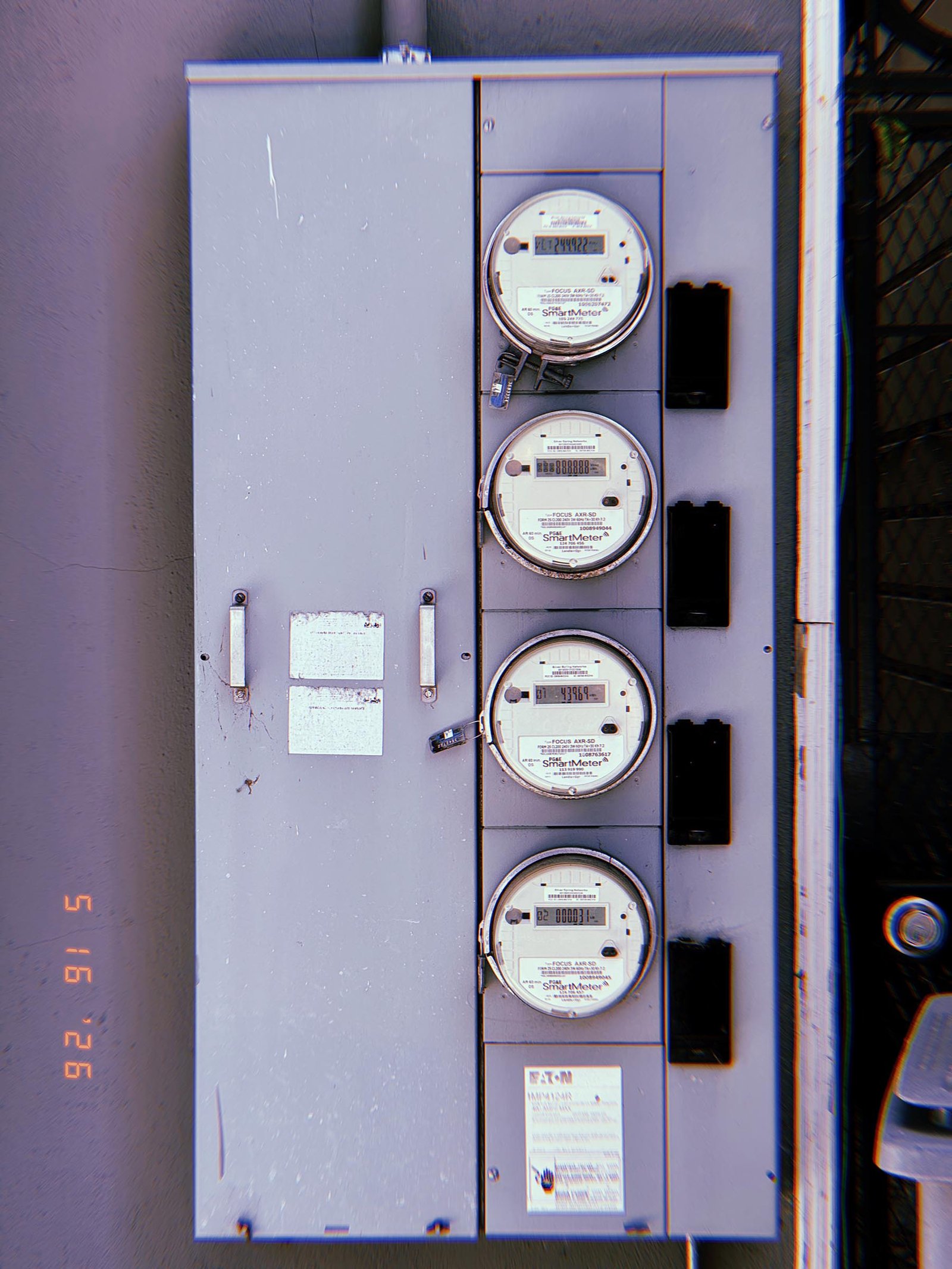
SF Modules – Set 020 – Electric Meter Systems – 08
SF Modules — Set 020 “Electric Meter Systems”.
Electrical consumption is monitored through a digital smart meter integrated into a service cabinet connected to the building distribution network. The meter records energy usage and transmits consumption data as part of the infrastructure linking individual properties to the broader electrical utility system.
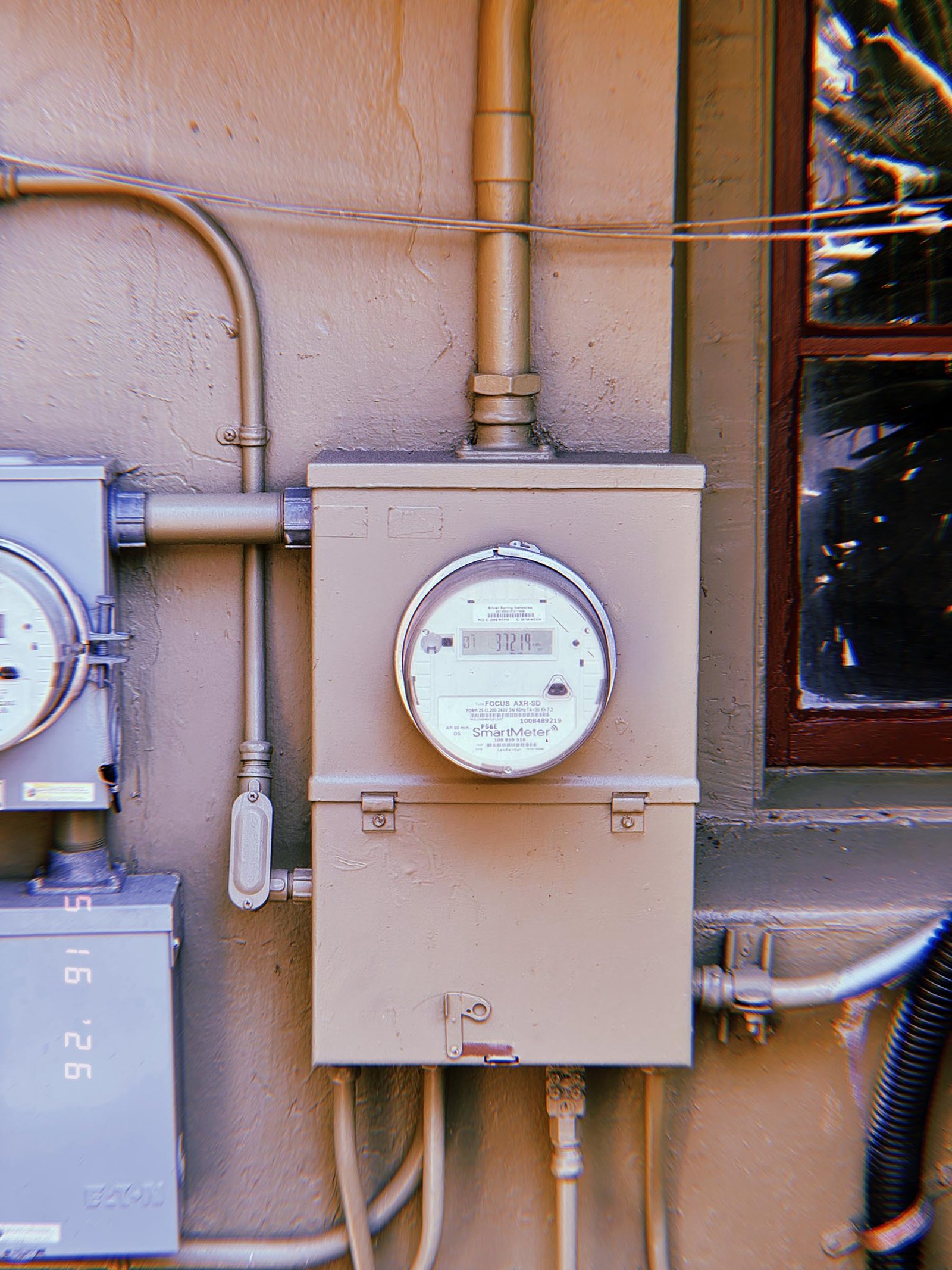
SF Modules – Set 020 – Electric Meter Systems – 09
SF Modules — Set 020 “Electric Meter Systems”.
Electrical consumption is measured through a network of digital metering devices connected to the distribution infrastructure of a building. Individual meters record energy use, enabling allocation, monitoring, and management of electrical consumption across separate service units within the larger utility system.